About Procedural Mesh Component
See
UProceduralMeshComponentSeeUKismetProceduralMeshLibrarySee this video for a example of slicing a procedural mesh component.
A procedural mesh is composed of multiple sections (FProcMeshSection).
Sections
Each section holds some data such as the vertices (FProcMeshVertex), collisions (bEnableCollision) and more.
Each material has its own section (you can get/set the material of a section by using the section index or by reading the value of MaterialIndex on the FSkelMeshRenderSection entry.
When you use the various CreateMeshSection functions you might wonder what each param is.
Here is a description for the important ones:
- Vertices: All the vertices for the section you are making, since you are using triangles this array should always be a multiple of 3 (not enforced, you might want to have extra vertices for some other use).
- Triangles: For each triangle (3 entry per triangle, same as Vertices) tell what vertices should be used for each triangle corner. For example if you want 1 triangle and you have 3 entries in Vertices, your Triangles array should be
{0, 1, 2}. - VertexColors: Tell the color to be used for each vertex. This should match the size of Vertices.
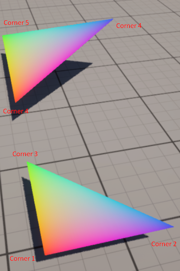
Order of vertices indexes/triangles corners important
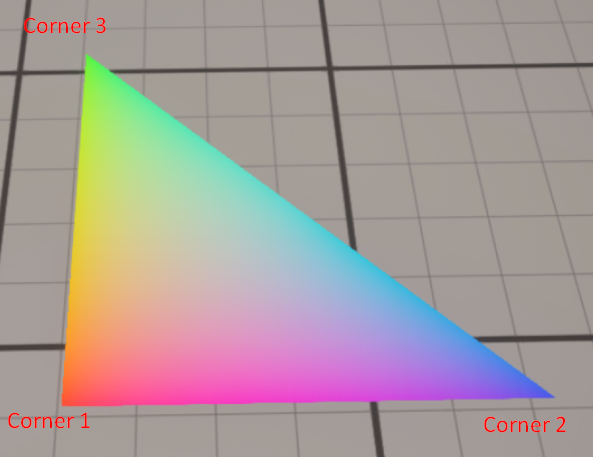
The order of your vertices are important and must “match” to not have some inverted normals/faces. This depends on your normal values As you can see more clearly in the “simple triangle” and “reuse vertices” examples below, the triangle is expected to be built in a specific order (Corner 1 → Corner 2 → Corner 3). Corner 1 would be the origin point, it doesnt have any order conditions.
In case of the normal value being
0,0,1Corner 2 is the “right” corner. Corner 3 is the “forward” corner. This means that Corner 3 should have the biggest relative X value, and Corner 2 should have the biggest relative Y value.In case of the normal value being
0,0,-1Corner 2 is the “left” corner. Corner 3 is the “bottom” corner. This means that Corner 3 should have the lowest relative X value, and Corner 2 should have the lowest relative Y value.
Vertices
FProcMeshVertex hold per vertex data such as the position, normal, UVs and more.
Examples
Simple triangle
I have a list of sections to create, in this example we only have one entry.
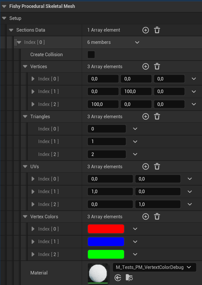
Those values were set by the default section constructor (a custom type I made)
// Relevant code \\

// our 3 vertices, representing the 3 points of our triangle
Vertices.Emplace(FVector(0, 0, 0));
Vertices.Emplace(FVector(0, 100, 0));
Vertices.Emplace(FVector(100, 0, 0));

// the indexes of the 3 vertices (inside Vertices) that will be used for this triangle
Triangles.Emplace(0);
Triangles.Emplace(1);
Triangles.Emplace(2);

// UVs for this triangle (optional in our case)
UVs.Emplace(FVector2D(0, 0));
UVs.Emplace(FVector2D(1, 0));
UVs.Emplace(FVector2D(0, 1));

// colors for each vertex
VertexColors.Emplace(FColor::Red);
VertexColors.Emplace(FColor::Blue);
VertexColors.Emplace(FColor::Green);

// The 3 normal array entries are set to 0,0,1
Then I call a function on BeginPlay that creates the new sections from the data.
void UPSMTestProceduralMeshComponent::CreateMeshFromData()
{
	ClearAllMeshSections();

	// Assign the geometry data to the mesh component
	for (int i = 0; i < SectionsData.Num(); ++i)
	{
		auto& CurrentSection = SectionsData[i];
		CurrentSection.CalcNormals();

		CreateMeshSection_LinearColor(
			0,
			CurrentSection.Vertices,
			CurrentSection.Triangles,
			CurrentSection.Normals,
			CurrentSection.UVs,
			CurrentSection.VertexColors,
			TArray<FProcMeshTangent>(),
			CurrentSection.bCreateCollision
		);
		SetMaterial(i, CurrentSection.Material);
	}
}
Why using a material ? You are already giving the colors with
VertexColors.Well if you don’t supply any material the engine will default to the default grid material. You can use whatever material you want however if you want to see the values you set in
VertexColorsyou should use theVertexColormaterial Node like so:
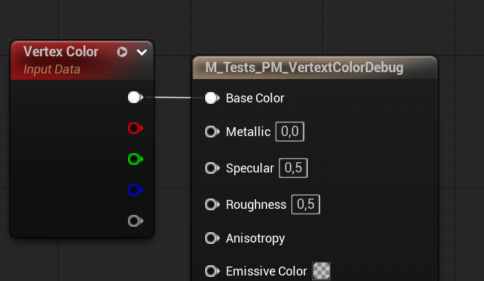
And here is the result:
2 simple triangles
Using the same code with different values as showed in the simple triangle example:
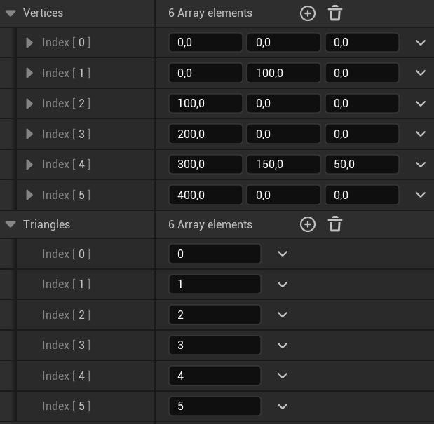
Result:
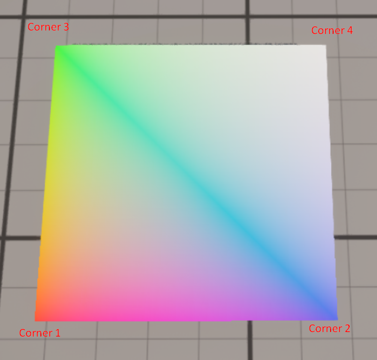
Reusing vertex for close triangle (square case)
In some cases you want 2 (or more) triangles to be next to each other (for example to make a square).
In this square example we will add 1 vertex to our first 3 and reuse 2 of the previous vertices for our new triangle.
The data is the following:
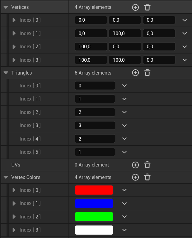
Result:
Skeletal Mesh
You can generate a mesh looking the same as a Skeletal Mesh from a Skeletal Mesh Component.
Warning
Before doing further please note that this is some early testing code that “works”. For physics you shouldn’t use this mesh collisions and physics but add bigger bodies like the Skeletal Mesh Component does.
Code (primarily taken from this UE forum post):
void UPSMTestProceduralSkeletalMeshComponent::CreateProceduralSkeletalMeshFromData(USkeletalMeshComponent* SkeletalMeshComponent, int32 LODIndex)
{
	if (!IsValid(SkeletalMeshComponent)) { return; }

	FSkeletalMeshRenderData* SKMRenderData = SkeletalMeshComponent->GetSkeletalMeshRenderData();
	const FSkeletalMeshLODRenderData& DataArray = SKMRenderData->LODRenderData[LODIndex];
	FSkinWeightVertexBuffer& SkinWeights = *SkeletalMeshComponent->GetSkinWeightBuffer(LODIndex);

	TArray<FVector> VerticesArray;
	TArray<FVector> Normals;
	TArray<FVector2D> UV;
	TArray<FColor> Colors;
	TArray<FProcMeshTangent> Tangents;
	TArray<UMaterialInterface*> Materials;

	for (int32 ReaderSectionIndex = 0; ReaderSectionIndex < DataArray.RenderSections.Num(); ReaderSectionIndex++)
	{
		const auto& SectionData = DataArray.RenderSections[ReaderSectionIndex];

		// get num vertices and offset
		const int32 NumSourceVertices = SectionData.NumVertices;
		const int32 BaseVertexIndex = SectionData.BaseVertexIndex;

		Materials.Emplace(SkeletalMeshComponent->GetMaterial(SectionData.MaterialIndex));

		for (int32 i = 0; i < NumSourceVertices; i++)
		{
			const int32 VertexIndex = i + BaseVertexIndex;

			// get skinned vector positions
			const FVector3f SkinnedVectorPos = USkeletalMeshComponent::GetSkinnedVertexPosition(
				SkeletalMeshComponent, VertexIndex, DataArray, SkinWeights);
			VerticesArray.Emplace(SkinnedVectorPos.X, SkinnedVectorPos.Y, SkinnedVectorPos.Z);

			// Calc normals and tangents from the static version instead of the skeletal one
			const FVector3f ZTangentStatic = DataArray.StaticVertexBuffers.StaticMeshVertexBuffer.VertexTangentZ(
				VertexIndex);
			const FVector3f XTangentStatic = DataArray.StaticVertexBuffers.StaticMeshVertexBuffer.VertexTangentX(
				VertexIndex);

			// add normals from the static mesh version instead because using the skeletal one doesnt work right.
			Normals.Emplace(ZTangentStatic.X, ZTangentStatic.Y, ZTangentStatic.Z);

			// add tangents
			Tangents.Add(FProcMeshTangent(FVector(XTangentStatic.X, XTangentStatic.Y, XTangentStatic.Z), false));

			// get UVs
			const FVector2f SourceUVs = DataArray.StaticVertexBuffers.StaticMeshVertexBuffer.GetVertexUV(VertexIndex, 0);
			UV.Emplace(SourceUVs);

			// dummy vertex colors
			Colors.Add(FColor::Red);
		}
	}

	// get index buffer
	FMultiSizeIndexContainerData IndicesData;
	DataArray.MultiSizeIndexContainer.GetIndexBuffer(IndicesData.Indices);


	for (int32 RenderSectionIndex = 0; RenderSectionIndex < DataArray.RenderSections.Num(); RenderSectionIndex++)
	{
		const auto& SectionData = DataArray.RenderSections[RenderSectionIndex];
		TArray<int32> Tris;

		// get number triangles and offset
		const int32 SectionNumTriangles = SectionData.NumTriangles;
		const int32 SectionBaseIndex = SectionData.BaseIndex;

		// iterate over num indices and add traingles
		for (int32 i = 0; i < SectionNumTriangles; i++)
		{
			int32 TriVertexIndex = i*3 + SectionBaseIndex;
			Tris.Add(IndicesData.Indices[TriVertexIndex]);
			Tris.Add(IndicesData.Indices[TriVertexIndex + 1]);
			Tris.Add(IndicesData.Indices[TriVertexIndex + 2]);
		}

		// Create the procedural mesh section
		CreateMeshSection(RenderSectionIndex, VerticesArray, Tris, Normals, UV, Colors, Tangents, bCreateCollision);
		SetMaterial(RenderSectionIndex, Materials[RenderSectionIndex]);
	}

	if (bSimulatePhysics)
	{
		SetSimulatePhysics(true);
	}
}